
01Radius
Inside radius
Set a practical radius for the material and thickness; tooling and forming method determine the achieved value.
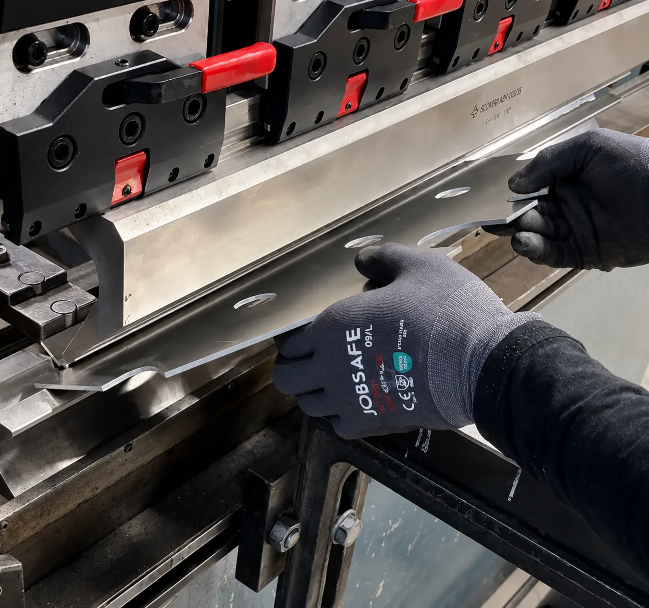
Upload the formed part, choose an eligible material and thickness, and keep laser cutting, bend geometry and finishing in one production flow.
Supply the formed STEP geometry or a drawing that shows bend direction, angle, inside radius and the flange dimensions that matter. Metalldel develops and reviews the blank against the selected material and available tooling.
The quote is based on a manufacturable sequence, not only a visible final shape. Short flanges, returns, nearby holes and tool collisions are checked before the part is accepted for online production.
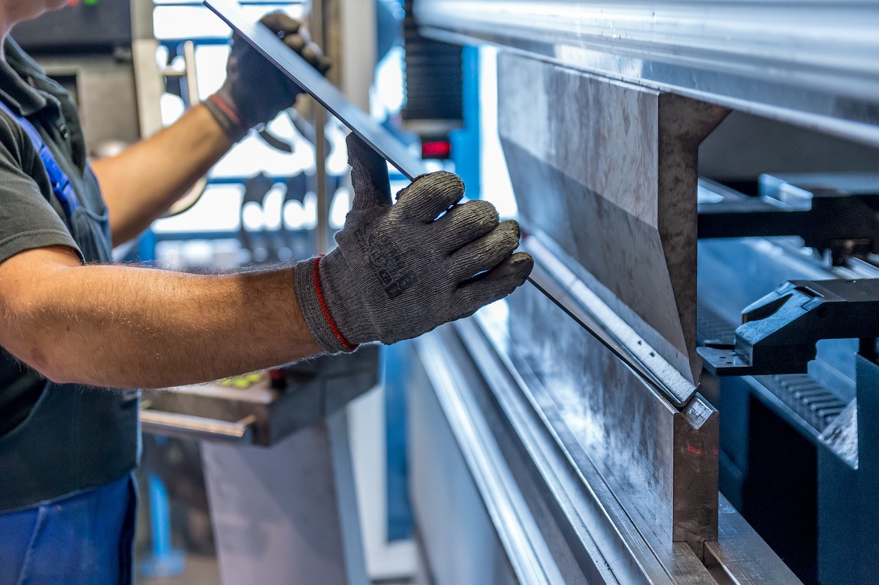
Set a practical radius for the material and thickness; tooling and forming method determine the achieved value.
A flange must reach the die and backgauge correctly. Very short legs may require another tool or design change.
Holes, slots and notches can stretch or distort when placed too close to the deformation zone.
Rolling direction and material strength can affect cracking risk, bend force and angular springback.
Loading current material availability…
Bend eligibility also depends on flange length, radius, tool access and sequence.
| Thickness (t) | V-opening (8 × t) | Inside radius (≈ 1 × t) | Minimum flange (≈ 4 × t) | Hole from bend line (2–3 × t) |
|---|---|---|---|---|
| 1.0 | 8 | ≈ 1.0 | ≈ 4 | 2–3 |
| 1.5 | 12 | ≈ 1.5 | ≈ 6 | 3–4.5 |
| 2.0 | 16 | ≈ 2.0 | ≈ 8 | 4–6 |
| 3.0 | 24 | ≈ 3.0 | ≈ 12 | 6–9 |
| 4.0 | 32 | ≈ 4.0 | ≈ 16 | 8–12 |
| 5.0 | 40 | ≈ 5.0 | ≈ 20 | 10–15 |
| 6.0 | 48 | ≈ 6.0 | ≈ 24 | 12–18 |
Reference only: stainless steel and aluminium can require different radii, bend allowances and springback compensation. Short flanges, features near a bend, return bends and tight profiles are reviewed against the actual tooling.
One controlled bend for brackets, flanges and simple angle profiles.
Multiple bends require a planned order so previously formed flanges remain clear of the tooling.
Tight returns and closed profiles need tool-access review and may require special tooling or a revised geometry.
Confirm bend lines, direction, angles, radii and critical dimensions.
Apply material- and process-specific bend allowance to the flat pattern.
Select punch, die and operation order while checking collision and flange access.
Bend the part and check the agreed angle and dimensional requirements.
Upload the finished 3D geometry with the intended material, thickness, bend radii and angles. STEP is preferred when the formed shape must be analysed.
Clearance depends on thickness, radius and tooling. Use the bending table as a starting point; the submitted geometry receives the final check.
Provide the finished part geometry. Metalldel evaluates eligible bends and the production blank against the configured material and tooling.
Short flanges, tool access, collisions, closed shapes and features near bends can require a production decision before pricing.
Upload the formed geometry and let the material, tooling and sequence be reviewed together.