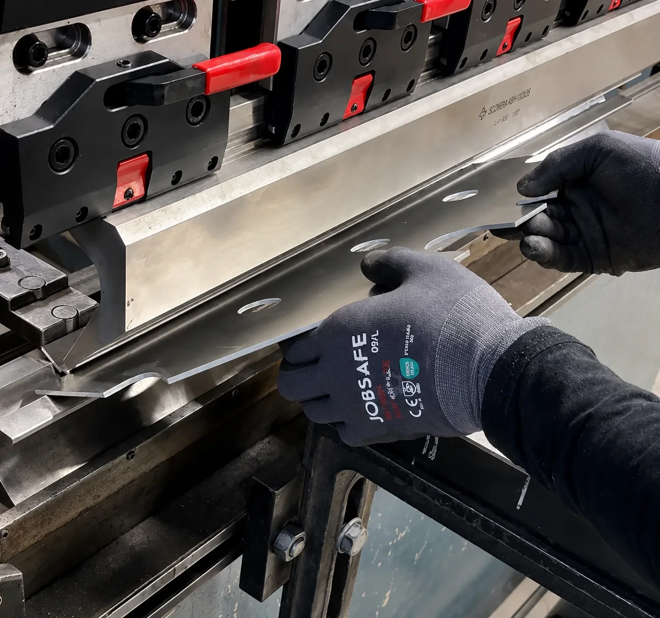
A bend cannot be assessed from its angle alone. Material, thickness, inside radius, flange lengths, nearby features, and the sequence of multiple bends all affect how the part can be formed. A clear input makes it possible to review those conditions together.
1. Show the finished shape
Use formed STEP or STP geometry when the three-dimensional shape must be analysed. A drawing can supplement the model with dimensions and requirements that are not unambiguous in the geometry. A flat pattern alone does not show the finished shape; if it is your only input, document bend lines and direction and ask Metalldel to review it before ordering.
- Bend direction for every bend
- Specified angle and relevant inside radius
- Critical finished dimensions and flange dimensions
- Which face is visible or has a directional finish"
- The material and thickness against which the part should be assessed
2. Look for features near the bend line
oles, slots, cut-outs, and short flanges can be affected by the forming zone or limit how the part can be positioned in the tooling. Do not move those features using a generic distance alone. Mark the functionally critical dimensions and have the submitted geometry assessed against the actual material and tooling.
3. Consider tool access and bend sequence
| Geometry | What needs to be clarified |
|---|---|
| Short flange | Whether the flange can be supported and reached with available tooling. |
| Hole or slot near a bend | Whether the feature lies in or near the forming zone and can be affected. |
| Return bend or closed profile | Whether a previously formed flange collides with the tooling or machine. |
| Multiple bends | Which sequence keeps the next bend accessible. |
| Directional surface | Which face and direction must be preserved as the visible result. |
4. Add a drawing when the model is not enough"
- Dimensioned finished dimensions that must be checked after bending
- Bend direction, angle, and inside radius where these are requirements
- Datum faces and which face should be outside or up
- Whether a dimension is critical, nominal, or for information only
- Short notes that do not conflict with the model
5. Check material and thickness together with the geometry
Achieved radius, required force, springback, and risk around features are influenced by material and thickness. A material appearing in the catalogue therefore does not mean that every geometry can be bent. Use the combinations shown in the configurator as the first filter and submit the specific part for final review.
6. Make this final check before ordering
- Compare the 3D model with the drawing and remove conflicting revisions.
- Check every bend direction, angle, radius, and critical flange dimension.
- Look for holes, slots, short flanges, return bends, and possible collisions.
- Document material, thickness, and the visible face in the model or drawing, then confirm the available material and finish choices in the configurator.
- Request a review if a functional requirement is not clear in the model and drawing.